Principles of Variable Frequency Drives (VFDs)
Compartir
Abstract
Variable Frequency Drives (VFDs) are essential components in modern industrial applications due to their efficiency and precise control capabilities. This paper explores the fundamental principles of VFD operation, providing a concise overview of how VFDs regulate power to control motor speed and optimize energy consumption. In-depth technical discussions will be presented in subsequent articles focusing on the
HRSTI series. Key concepts such as pulse-width modulation (PWM), voltage and frequency adjustment, and power conversion are discussed to provide a comprehensive understanding of VFD functionality.
Introduction
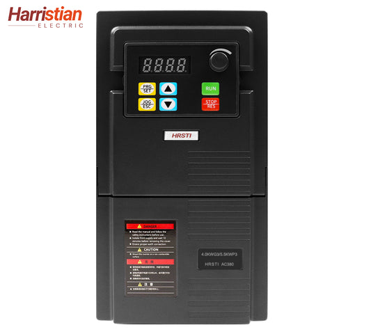
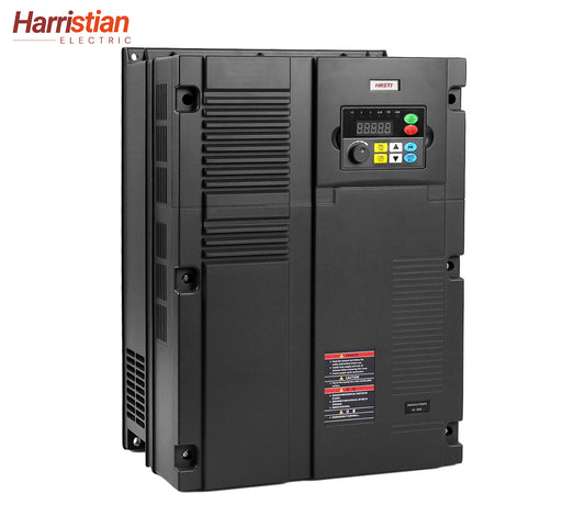
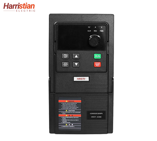
Variable Frequency Drives, also known as adjustable-speed drives, are electronic devices designed to control the rotational speed and torque of electric motors. VFDs accomplish this by varying the frequency and voltage of the electrical power supplied to the motor. Using the HRSTI series as an example, unlike conventional fixed-speed motor controllers,
HRSTI series VFDs offer precise and dynamic control, resulting in improved energy efficiency, reduced mechanical wear, and enhanced process control in industrial environments.
Operating Principle
The core operating principle of a VFD lies in its ability to control the frequency of the alternating current (AC) supplied to the motor. According to Kim, S. (2017), the synchronous speed of an AC motor can be calculated using the formula:

where N_s is the synchronous speed in revolutions per minute (RPM), f is the supply frequency in hertz (Hz), and P is the number of motor poles. By adjusting the supply frequency, a VFD can precisely control the motor speed (Kim, S. 2017).
A standard VFD consists of three main sections:
1. Rectifier Circuit: Converts incoming AC power to direct current (DC).
2. DC Bus (Filter): Smooths the DC voltage and reduces ripple.
3. Inverter Circuit: Converts the filtered DC back into AC at a controlled frequency and voltage using semiconductor switching devices such as IGBTs or MOSFETs.
Pulse-Width Modulation (PWM)
The inverter section employs Pulse-Width Modulation (PWM) to synthesize the AC output. PWM works by rapidly switching the power transistors on and off, generating a series of variable-width pulses that effectively mimic a sinusoidal waveform. This method allows for high-resolution control of motor speed while minimizing energy losses and reducing harmonic distortion.
Voltage and Frequency Control
To maintain efficient and stable motor operation, VFDs coordinate voltage and frequency through a constant V/f (voltage-to-frequency) ratio. This approach ensures stable magnetic flux within the motor, prevents saturation, and avoids overheating. For instance, when the frequency is reduced by half, the output voltage is also proportionally decreased to maintain optimal motor performance.
Applications
VFDs are extensively used across a range of industrial sectors. Taking the HRSTI 720 series as an example, typical applications include HVAC systems, conveyor belts, water pumps, air compressors, and various types of automated manufacturing equipment. The ability to dynamically control motor speed results in substantial energy savings, reduced mechanical stress, and extended equipment lifespan.
Conclusion
Variable Frequency Drives play a vital role in modern industrial systems by improving energy efficiency, lowering operational costs, and enabling precise motor control. A solid understanding of VFD principles—such as PWM and voltage-frequency synchronization—is essential for optimizing industrial automation and energy management. As technological advancements continue, VFDs will increasingly become a cornerstone of intelligent control and sustainable manufacturing.
Reference:
Kim, S. (2017) ‘Chapter 3/Alternating current motors: Synchronous motor and induction motor’, in Electric Motor Control: DC, AC, and BLDC Motors. Amsterdam, Netherlands: Elsevier, pp. 95–152.


